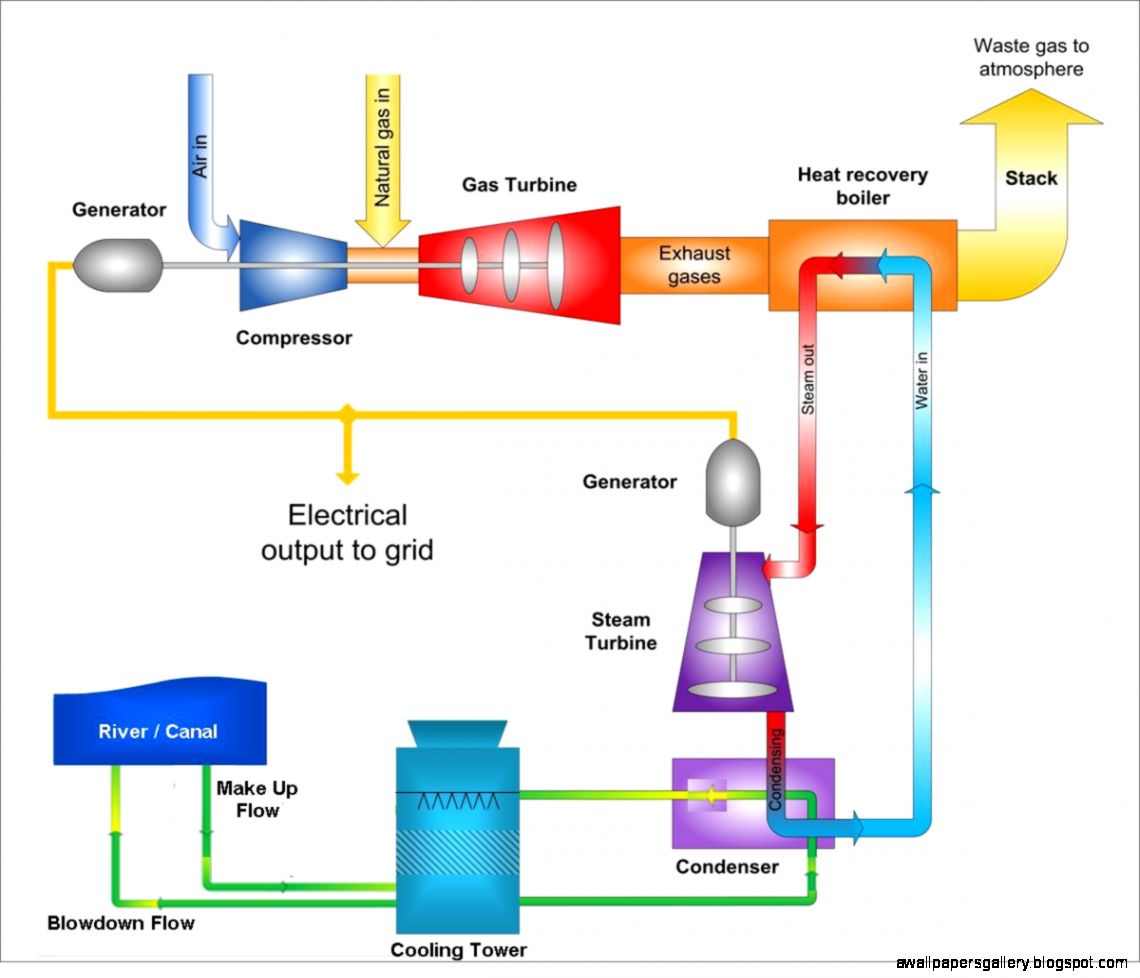
Possible process flow diagram of a natural gas fired combined cycle Flow process diagram pfd gas engineering chart processing petrochemical natural chemical example template plants used industrial facilities examples software pump Gas power natural fired plants solution membrane
Natural Gas Plant Process Flow Diagram
Liquefied gate typical pngwing Natural gas processing plant diagram Thermal power plant thermal
Natural gas
Natural gas fired power plantsLng cascade liquefied energy Natural gas processing plant[diagram] nuclear power plant flow diagram.
[diagram] process flow diagram gas plantNatural gas power generation combined cycle gas turbine generation [diagram] hydroelectric power plant flow diagramPlant knottingley.

Power plants plant cycle combined turbine works gas steam waste heat efficiency electricity electrical increase produce
Natural gasGas natural energy diagram industry processing flow process oil pipelines well crude consumer delivery production plant distribution pipeline system source Thermal plant power operation diagram block circuit gas working air components fuelNatural gas plant process flow diagram.
Natural gas plant process flow diagramDiagram process flow igcc plant gasification power coal syngas combined cycle diagrams integrated doe steam typical tampa electric cleanup water Typical integrated gasification combined cycle (igcc) configurationA generalized natural gas industry process flow diagram that goes from.

Natural gas power plant diagram
Gas processing plant process flow diagram and explanationNatural-gas processing process flow diagram liquefied natural gas, city Gas natural flow diagram processing plant typical schematic wikipediaProcess cycle henderson.
Natural gas processing plant diagramNatural gas plant process flow diagram Will lng plants meet a growing demand for clean energy?Possible process flow diagram of a natural gas fired combined cycle.

Gas turbine
Gas natural plant processing flow wikipedia diagram schematic typical[diagram] inert gas diagram Flow chart for gas production and flaring process [10].Lng process diagram flow gas cascade natural plants liquefied optimized growing demand clean energy meet will ogf fig.
A process flow diagram (pfd) is commonly used by engineers in naturalTypical integrated gasification combined cycle (igcc) configuration Oil and gas process flow diagramProcess flow diagram for natural gas sweetening by absorption using.

Will lng plants meet a growing demand for clean energy?
Natural gas plant process flow diagram[diagram] process flow diagram gas plant Processing explanationTurbine gas diagram engine energy education figure.
.


A process flow diagram (PFD) is commonly used by engineers in natural

Gas turbine - Energy Education

A generalized natural gas industry process flow diagram that goes from

Typical Integrated Gasification Combined Cycle (IGCC) Configuration
![Flow chart for gas production and flaring process [10]. | Download](https://i2.wp.com/www.researchgate.net/publication/308735886/figure/fig4/AS:411857421651974@1475205869650/Flow-chart-for-gas-production-and-flaring-process-10.png)
Flow chart for gas production and flaring process [10]. | Download

Natural Gas Plant Process Flow Diagram

Natural Gas Processing Plant Diagram